
There are a large number of alloys available with a wide range of physical and mechanical properties covering almost every conceivable application a designer might require. Available alloys include aluminum, zinc, zinc-aluminum, magnesium, copper, lead and tin. Die casting alloys are normally non-ferrous, and there is a large number available with a wide range of physical and mechanical properties covering almost every conceivable application a designer might require.
Aluminum and zinc alloys are the most widely used, and are followed by magnesium, zinc-aluminum (ZA) alloys, copper, tin and lead.
Zinc, lead and tin based alloys are classified as low melting point metals, all melting at less than 725°F (385°C). Zinc-aluminum (ZA) alloys have a slightly higher melting range of 800°F to 900°F (426°C to 482°C). Aluminum and magnesium alloys are considered to be moderate melting point alloys, being cast in the 1150°F to 1300°F (621°C to 704°C) range. Copper alloys are considered to be high melting point alloys, over 1650°F (899°C). Low melting point alloys are cast in hot chamber machines. Intermediate and high melting point alloys are cast in cold chamber machines. In recent years, specially designed hot chamber machines for die casting magnesium alloys have come into use.
Aluminum die casting alloys (Table1) are lightweight, offer good corrosion resistance, ease of casting, good mechanical properties and dimensional stability.
Although a variety of aluminum alloys made from primary or recycled metal can be die cast, most designers select standard alloys listed below:
360 — Selected for best corrosion resistance. Special alloys for special applications are available, but their use usually entails significant cost premiums.
380 — An alloy which provides the best combination of utility and cost.
383 & 384 — These alloys are a modification of 380. Both provide better die filling, but with a moderate sacrifice in mechanical properties, such as toughness.
390 — Selected for special applications where high strength, fluidity and wear-resistance/bearing properties are required.
413 (A13) — Used for maximum pressure tightness and fluidity.
| DESIGNATIONS | A360.0 | A380.0 | E380.0 | 383 | B383.0 | A413.0 | B390.0 | 384 |
| AA NUMBER | A360.0 | A380.0 | – | – | – | A13 | 390 | 384 |
| FORMER NO. | ||||||||
| COMPOSITION (in percent max. unless shown as range) | ||||||||
| Silicon | 9.0-10.0 | 7.5-9.5 | 7.5-9.5 | 9.5-11.5 | 9.5-11.5 | 11.0-13.0 | 16.0-18.0 | 10.5-12.0 |
| Iron | 1.3 | 1.3 | 1.3 | 1.3 | 1.3 | 1.3 | 1.3 | 1.3 |
| Copper | 0.6 | 3.0-4.0 | 3.0-4.0 | 2.0-3.0 | 2.0-3.0 | 1 | 4.0-5.0 | 3.0-4.5 |
| Manganese | 0.35 | 0.5 | 0.5 | 0.5 | 0.5 | 0.35 | 0.5 | 0.5 |
| Magnesium | 0.40-0.6 | 0.1 | 0.3 | 0.1 | 0.3 | 0.1 | 0.45-0.65 | 0.1 |
| Nickel | 0.5 | 0.5 | 0.5 | 0.3 | 0.3 | 0.5 | 0.1 | 0.5 |
| Zinc | 0.5 | 3 | 3 | 3 | 3 | 0.5 | 1.5 | 3 |
| Tin | 0.15 | 0.35 | 0.35 | 0.15 | 0.15 | 0.15 | 0.2 | 0.35 |
| Titanium | – | – | – | – | – | – | 0.2 | – |
| Total others | 0.25 | 0.5 | 0.5 | 0.5 | 0.5 | 0.25 | 0.20 (0.10 ea.) | 0.5 |
| Aluminum | Bal. | Bal. | Bal. | Bal. | Bal. | Bal. | Bal. | Bal. |
| PROPERTIES (see notes) | ||||||||
| Ultimate tensile strength (ksi) | 46 | 47 | 47 | 45 | 45 | 42 | 40.5 | 48 |
| Tensile yield strength (ksi) | 24 | 23 | 23 | 22 | 22 | 19 | 35 | 24 |
| Elongation (% in 2″ G.L.) | 3.5 | 3.5 | 3.5 | 3.5 | 3.5 | 3.5 | 1.0 2.5 | |
| Hardness (HB) | 75 | 80 | 80 | 80 | 80 | 120 | 85 | |
| Shear Strength (ksi) | 26 | 27 | 27 | 25 | 25 | 29 | ||
| Charpy impact strength (ft. lb.óunnotched) | 4.2 | 3.5 | 3.5 | 2 | ||||
| Fatigue strength (ksi) (limit @ 500 million cycles) | 18 | 20 | 20 | 19 | 19 | 20 | 20 | |
| Density (lb./in.3) | 0.95 | 0.98 | 0.98 | 0.97 | 0.97 | 0.96 | 0.99 | 0.98 |
| Melting range (oF) approx. | 1035-1105 | 1000-1100 | 1000-1100 | 960-1080 | 960-1080 | 1065-1080 | 945-1200 | 960-1080 |
| Specific heat (Btu/lb.oF) | 0.23 0.23 | 0.23 | 0.23 | |||||
| Coefficient of thermal expansion (in./in./oF) | 11.8 | 11.7 | 11.7 | 11.5 | 11.5 | 10.3 | 11.7 | 11.3 |
| Thermal conductivity (Btu/fthr.oF) | 65.3 | 55.6 | 55.6 | 55.6 | 55.6 | 67.7 | 78.6 | 56 |
| Electrical conductivity (% IACS) | 29 | 31 | 31 | 23 | 23 | 31 | 25 | 23 |
| Modulus of elasticity (106 psi) | 10.3 | 10.3 | 10.3 | 10.3 | 10.3 | 10.3 | 11.9 | 10.3 |
Zinc-based alloys are the easiest for die casting. Ductility is high and impact strength is excellent, making these alloys suitable for a wide range of products. Zinc die casting provides thin walls and excellent surface smoothness making preparation for plating and painting relatively easy.
It is essential that only high purity (99.99 + 0/0) zinc metal be used in the formulation of alloys. Low limits on lead, tin and cadmium ensure the long-term integrity of the alloy’s strength and dimensional stability.
| DESIGNATIONS
COMPOSITION (in percent max. unless shown as range for die castings) … for ingots |
ZAMAK 2 |
ZAMAK 3 |
ZAMAK 5 |
ZAMAK 7 |
ZA-8 |
ZA-12 |
ZA-27 |
| Aluminum |
3.7-4.3 |
3.5-4.3 |
3.5-4.3 |
3.5-4.3 |
8.0-8.8 |
10.5-11.5 |
25.0-28.0 |
| Copper |
2.6-3.3 |
0.25 |
0.75-1.25 |
0.25 |
0.8-1.3 |
0.5-1.25 |
2.0-2.5 |
| Magnesium |
0.02-0.06 |
0.02-0.05 |
0.03-0.08 |
0.005-0.020 |
0.015-0.030 |
0.015-030 |
.010-.020 |
| Iron |
0.05 |
0.1 |
0.1 |
0.075 |
0.1 |
0.075 |
0.1 |
| Lead |
0.005 |
0.005 |
0.005 |
0.003 |
0.004 |
0.004 |
0.004 |
| Cadmium |
0.004 |
0.004 |
0.004 |
0.002 |
0.003 |
0.003 |
0.003 |
| Tin |
0.002 |
0.003 |
0.003 |
0.001 |
0.002 |
0.002 |
0.002 |
| Nickel |
0 |
0 |
0 |
0.005-0.020 |
0 |
0 |
0 |
| Zinc |
Bal. |
Bal. |
Bal. |
Bal. |
Bal. |
Bal. |
Bal. |
| PROPERTIES (see notes)
|
|||||||
| Ultimate tensile strength (ksi) |
52 |
40 |
48 |
41 |
54 |
58.5 |
61 |
| Tensile yield strength (ksi) |
41 |
32 |
39 |
32 |
42 |
46 |
53 |
| Elongation (% in 2″ (55 mm)) |
7 |
10 |
7 |
13 |
10-Jun |
7-Apr |
3-Jan |
| Hardness (HB) |
100 |
82 |
91 |
80 |
95-110 |
95-115 |
105-125 |
| Shear strength (ksi) |
46 |
31 |
38 |
0 |
35 |
37 |
42 |
| Charpy impact strength (ft. lb.óunnotched) |
35 |
43 |
48 |
43 |
31 |
21 |
3 |
| Fatigue strength (ksi) (limit @ 500 million cycles) |
8.5 |
6.9 |
8.2 |
0 |
7.5 |
15 |
25 |
| Density (lb./in.3) |
0.24 |
0.24 |
0.24 |
0.247 |
0.227 |
0.218 |
0.181 |
| Melting range (oF) |
715-734 |
718-728 |
717-727 |
718-728 |
707-759 |
710-810 |
708-903 |
| Specific heat (Btu/lb.oF) |
0.1 |
0.1 |
0.1 |
0.1 |
0.104 |
0.107 |
0.125 |
| Coefficient of thermal expansion (in./in./oF) |
15.4 |
15.2 |
15.2 |
15.2 |
12.9 |
13.4 |
14.4 |
| Thermal conductivity (Btu/fthr.oF) |
60.5 |
65.3 |
62.9 |
65.3 |
66.3 |
67.1 |
72.5 |
| Electrical conductivity (% IACS) |
25.0 |
27 |
26 |
27 |
27.7 |
28.3 |
29.7 |
| Modulus of elasticity (106 psi) |
0 |
0 |
0 |
0 |
10.2 |
10.3 |
10.3 |
| Die shrinkage (in./in.) |
0.007 |
0.007 |
0.007 |
0.007 |
0.007 |
0.0075 |
0.008 |
| – A – | |||||||||
| Automation — Industry term commonly used to describe the mechanization of various aspects of the die casting process. | |||||||||
| – B – | |||||||||
| Biscuit — Excess of ladled metal remaining in the shot sleeve of a cold chamber die casting machine. It is part of the cast shot and is removed from the die with the casting. | |||||||||
| Blister — A surface bubble caused by gas expansion (usually from heating) which was trapped within the die casting or beneath the plating. | |||||||||
| Blow holes — Voids or pores which may occur due to entrapped gas or shrinkage during solidification, usually evident in heavy sections (see porosity). | |||||||||
| – C – | |||||||||
| Cavity — The recess or impressions in a die in which the casting is formed. | |||||||||
| Cold chamber machine — A type of casting machine in which the metal injection mechanism is not submerged in molten metal. | |||||||||
| Checking — Fine cracks on the surface of a die which produce corresponding raised veins on die castings. Checking is caused by repeated heating of the die surface by injected molten alloys. | |||||||||
| Creep — Plastic deformation of metals held for long periods at stresses lower than yield strength. | |||||||||
| – D – | |||||||||
| Die lubricant — Liquid formulations applied to the die to facilitate casting release and prevent soldering. | |||||||||
| Dimensional stability — Ability of a component to retain its shape and size over a long period in service. | |||||||||
| Dowel pin — A guide pin which assures registry between cavities in two die halves. | |||||||||
| Draft — The taper given to walls, cores and other parts of the die cavity to permit easy ejection of the casting. | |||||||||
| – E – | |||||||||
| Ejector marks — Marks left on castings by ejector pins. | |||||||||
| Ejector plate — A plate to which ejector pins are attached and which actuates them. | |||||||||
| – F – | |||||||||
| Fillet — Curved junction of two surfaces, e.g., walls which would meet at a sharp angle. | |||||||||
| Flash — A thin web or fin of metal on a casting which occurs at die partings, vents and around moveable cores. This excess metal is due to working and operating clearances in a die. | |||||||||
| – G – | |||||||||
| Gate — Passage for molten metal which connects runner with die cavity. Also, the entire ejected content of a die, including castings, gates, runners, sprue (or biscuit) and flash. | |||||||||
| Gooseneck — Spout connecting a metal pot or chamber with a nozzle or sprue hole in the die and containing a passage through which molten metal is forced on its way to the die. It is the metal injection mechanism in a hot chamber type of die casting machine. | |||||||||
| Growth — Expansion of a casting as a result of aging or of intergranular corrosion, or both. | |||||||||
| – H – | |||||||||
| Heat checking — (see checking) | |||||||||
| Hot chamber machines — Die casting machines which have the plunger, gooseneck (metal pressure chamber) immersed in molten metal in the holding furnace. | |||||||||
| Hot short — Term used to describe an alloy which is brittle or lacks strength at elevated temperatures. | |||||||||
| – I – | |||||||||
| Impact strength — Ability to resist shock, as measured by a suitable testing machine. | |||||||||
| Impression — Cavity in a die. Also, the mark or recess left by a ball, or penetrator of a hardness tester. | |||||||||
| Ingot — Metal or alloy cast in a convenient shape for storage, shipping and remelting. | |||||||||
| Injection — The process of forcing molten metal into a die. | |||||||||
| Insert — A piece of material, usually metal, which is placed in a die before each shot. When molten metal is cast around it, it becomes an integral part of the die casting. | |||||||||
| Intergranular corrosion — A type of corrosion which preferentially attacks grain boundaries of metals or alloys, resulting in deep penetration. | |||||||||
| – J – | |||||||||
| (none) | |||||||||
| – K – | |||||||||
| (none) | |||||||||
| – L – | |||||||||
| Loose piece, knockout — A type of core (which forms undercuts) which is positioned in, but not fastened to a die. It is so arranged as to be ejected with the casting from which it is removed. It is used repeatedly for the same purpose. | |||||||||
| – M – | |||||||||
| Metal saver — Core used primarily to reduce amount of metal in a casting and to avoid sections of excessive thickness. | |||||||||
| Multiple cavity die — A die having more than one duplicate impression. | |||||||||
| – N – | |||||||||
| Nozzle — Outlet end of a gooseneck or the tubular fitting which joins the gooseneck to the sprue hole. | |||||||||
| – O – | |||||||||
| Overflow-well — A recess in a die connected to a die cavity by a gate to assist in proper venting. | |||||||||
| – P – | |||||||||
| Parting line — A mark left on a die casting where the die halves meet; also, the mating surface of the cover and ejector portions of the die. | |||||||||
| Plunger — Ram or piston which forces molten metal into a die. | |||||||||
| Port — Opening through which molten metal enters the injection cylinder. | |||||||||
| Porosity — Voids or pores resulting from trapped gas, or shrinkage during solidification. | |||||||||
| Process control — Where parameters of a process are studied and correctly applied in the manufacturing process to produce high quality parts. | |||||||||
| – Q – | |||||||||
| (none) | |||||||||
| – R – | |||||||||
| Runner — Die passage connecting sprue or plunger holes of a die to the gate where molten metal enters the cavity or cavities. | |||||||||
| – S – | |||||||||
| Shot — The segment of the casting cycle in which molten metal is forced into the die. | |||||||||
| Shrinkage, solidification — Dimensional reduction that accompanies the freezing (solidification) of metal passing from the molten to the solid state. | |||||||||
| Shrink mark — A surface depression which sometimes occurs next to a heavy section that cools more slowly than adjacent areas. | |||||||||
| Slide — The portion of the die arranged to move parallel to die parting. The inner end forms a part of the die cavity wall that involves one or more undercuts and sometimes includes a core or cores. | |||||||||
| Soldering — Adherence of molten metal to portions of the die. | |||||||||
| Split gate — A gate of castings having the sprue or plunger axis in the die parting. | |||||||||
| Sprue — Metal that fills the conical passage (sprue hole) which connects the nozzle with runners. | |||||||||
| Sprue pin — A tapered pin with a rounded end projecting into a sprue hole and acting as a core which deflects metal and aids in the removal of the sprue. | |||||||||
| Stability, dimensional — (see dimensional stability) | |||||||||
| – T – | |||||||||
| Toggle — Linkage employed to mechanically multiply pressure when locking the dies of a casting machine. | |||||||||
| Trim die — A die for shearing or shaving flash from a die casting. | |||||||||
| – U – | |||||||||
| Unit die — A die interchangeable with others in a common holder. | |||||||||
| Undercut — Recess in the side wall or cored hole of a casting disposed so that a slide or special form of core (such as a knockout) is required to permit ejection of the casting from the die. | |||||||||
| – V – | |||||||||
| Vent — Narrow passage at the die parting which permits air to escape from the die cavity as it is filled with molten metal. | |||||||||
| Void — A large pore or hole within the wall of a casting usually caused by entrapped gas. A blow hole. | |||||||||
| – W – | |||||||||
| Waterline — A tube or passage through which water is circulated to cool a casting die. | |||||||||
| – X – | |||||||||
| (none) | |||||||||
| – Y – | |||||||||
| (none) | |||||||||
| – Z – | |||||||||
| (none) | |||||||||
ADDITIONAL RESOURCES
One of the principal resources for additional information about die casting is the North American Die Casting Association. NADCA is the only trade association in the United States that represents all major segments of the die casting industry. Its goals include advancing the technology of the die casting process and providing information to its members and the general public. For more information, visit www.diecasting.org.
In addition, a “Design for Die Casting” CD-ROM is available. This CD provides technical information, video clips, computer graphic simulations and audio explaining die casting.
PUBLICATIONS
NADCA has a number of books available that provide more detailed information about die casting.
Introduction to Die Casting: A detailed overview of the industry, including the die casting process, machinery, quality, safety and costs. 1999©.
Die Casting Handbook: General technical information about die casting, as well as markets served and environmental issues. 2001©.
Dictionary of Die Casting Terms: Extensive listing of industry terms. 1998©.
Click below to read through frequently asked questions provided by the North American Die Casting Association.
Introduction to Die Casting
Die casting is a versatile process for producing engineered metal parts by forcing molten metal under high pressure into reusable steel molds. These molds, called dies, can be designed to produce complex shapes with a high degree of accuracy and repeatability. Parts can be sharply defined, with smooth or textured surfaces, and are suitable for a wide variety of attractive and serviceable finishes.
Die castings are among the highest volume, mass-produced items manufactured by the metalworking industry, and they can be found in thousands of consumer, commercial and industrial products. Die cast parts are important components of products ranging from automobiles to toys. Parts can be as simple as a sink faucet or as complex as a connector housing.
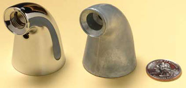
Figure 1: Die cast parts are found in many places around the home. The polished, plated zinc die casting in this kitchen faucet illustrates one of the many finishes possible with die casting.
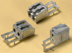
Figure 2: These connector housings are examples of the durable, highly accurate components that can be produced with today’s modern die casting.
The History of Die Casting
The earliest examples of die casting by pressure injection – as opposed to casting by gravity pressure – occurred in the mid-1800s. A patent was awarded to Sturges in 1849 for the first manually operated machine for casting printing type. The process was limited to printer’s type for the next 20 years, but development of other shapes began to increase toward the end of the century. By 1892, commercial applications included parts for phonographs and cash registers, and mass production of many types of parts began in the early 1900s.
The first die casting alloys were various compositions of tin and lead, but their use declined with the introduction of zinc and aluminum alloys in 1914. Magnesium and copper alloys quickly followed, and by the 1930s, many of the modern alloys still in use today became available.
The die casting process has evolved from the original low-pressure injection method to techniques including high-pressure casting – at forces exceeding 4500 pounds per square inch – squeeze casting and semi-solid die casting. These modern processes are capable of producing high integrity, near net-shape castings with excellent surface finishes.
THE FUTURE OF DIE CASTING
Refinements continue in both the alloys used in die casting and the process itself, expanding die casting applications into almost every known market. Once limited to simple lead type, today’s die casters can produce castings in a variety of sizes, shapes and wall thicknesses that are strong, durable and dimensionally precise.
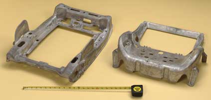
Figure 1: A magnesium seat pan shows how complex, lightweight die cast components can improve production by replacing multiple pieces.
Figure 2
What is Die Casting?
Die casting is a manufacturing process for producing accurately dimensioned, sharply defined, smooth or textured-surface metal parts. It is accomplished by forcing molten metal under high pressure into reusable metal dies. The process is often described as the shortest distance between raw material and finished product. The term “die casting” is also used to describe the finished part.
The term “gravity die casting” refers to castings made in metal molds under a gravity head. It is known as permanent mold casting in the U.S.A. and Canada. What we call “die casting” here is known as “pressure die casting” in Europe.
- How Are Die Castings Produced?
- Types Of Machines for Die Casting
- Hot Chamber Machines
- Cold Chamber Machines
- Casting Dies and Their Construction
- Die Terminology
- Types of Dies
- Automation in Die Casting
- Quality in Die Casting
- Continuous Computerized Process Monitoring
HOW ARE DIE CASTINGS PRODUCED?
First, a steel mold capable of producing tens of thousands of castings in rapid succession must be made in at least two sections to permit removal of castings. These sections are mounted securely in a machine and are arranged so that one is stationary (fixed die half) while the other is moveable (injector die half). To begin the casting cycle, the two die halves are clamped tightly together by the die casting machine. Molten metal is injected into the die cavity where it solidifies quickly. The die halves are drawn apart and the casting is ejected. Die casting dies can be simple or complex, having moveable slides, cores, or other sections depending on the complexity of the casting.
The complete cycle of the die casting process is by far the fastest known for producing precise non-ferrous metal parts. This is in marked contrast to sand casting which requires a new sand mold for each casting. While the permanent mold process uses iron or steel molds instead of sand, it is considerably slower, and not as precise as die casting.
TYPES OF MACHINES FOR DIE CASTING
Regardless of the type of machine used, it is essential that die halves, cores and/or other moveable sections be securely locked in place during the casting cycle. Generally, the clamping force of the machine is governed by (a) the projected surface area of the casting (measured at the die parting line) and (b) the pressure used to inject metal into the die. Most machines use toggle type mechanisms actuated by hydraulic cylinders (sometimes air pressure) to achieve locking. Others use direct acting hydraulic pressure. Safety interlock systems are used to prevent the die from opening during the casting cycles.
Die casting machines, large or small, vary fundamentally only in the method used to inject molten metal into the die. These are classified and described as either hot or cold chamber die casting machines.
HOT CHAMBER MACHINES
Hot chamber machines (Fig.1) are used primarily for zinc, and low melting point alloys which do not readily attack and erode metal pots, cylinders and plungers. Advanced technology and development of new, higher temperature materials has extended the use of this equipment for magnesium alloys.
In the hot chamber machine, the injection mechanism is immersed in molten metal in a furnace attached to the machine. As the plunger is raised, a port opens allowing molten metal to fill the cylinder. As the plunger moves downward sealing the port, it forces molten metal through the gooseneck and nozzle into the die. After the metal has solidified, the plunger is withdrawn, the die opens, and the resulting casting is ejected.
Hot chamber machines are rapid in operation. Cycle times vary from less than one second for small components weighing less than one ounce, to thirty seconds for a casting of several pounds. Dies are filled quickly (normally between five and forty milliseconds) and metal is injected at high pressures (1,500 to over 4,500 psi). Nevertheless, modern technology gives close control over these values, thus producing castings with fine detail, close tolerances and high strength.
Figure 1: Hot Chamber Machine. Diagram illustrates the plunger mechanism which is submerged in molten metal. Modern machines are hydraulically operated and equipped with automatic cycling controls and safety devices.

COLD CHAMBER MACHINES
Cold chamber machines (Fig. 2) differ from hot chamber machines primarily in one respect; the injection plunger and cylinder are not submerged in molten metal. The molten metal is poured into a “cold chamber” through a port or pouring slot by a hand or automatic ladle. A hydraulically operated plunger, advancing forward, seals the port forcing metal into the locked die at high pressures. Injection pressures range from 3,000 to over 10,000 psi for both aluminum and magnesium alloys, and from 6,000 to over 15,000 psi for copper-based alloys.
In a cold chamber machine, more molten metal is poured into the chamber than is needed to fill the die cavity. This helps sustain sufficient pressure to pack the cavity solidly with casting alloy. Excess metal is ejected along with the casting and is part of the complete shot.
Operation of a “cold chamber” machine is a little slower than a “hot chamber” machine because of the ladling operation. A cold chamber machine is used for high melting point casting alloys because plunger and cylinder assemblies are less subject to attack since they are not submerged in molten metal.
Figure 2: Cold Chamber Machine. Diagram illustrates die, cold chamber and horizontal ram or plunger (in charging position).

CASTING DIES AND THEIR CONSTRUCTION
Die casting dies (Fig. 3) are made of alloy tool steels in at least two sections called fixed die half and ejector die half. The fixed die half is mounted on the side toward the molten metal injection system. The ejector die half, to which the die casting adheres, and from which it is ejected when the die is opened, is mounted on the moveable platen of the machine.
The fixed die half of the die is designed to contain the sprue hole through which molten metal enters the die. The ejector half usually contains the runners (passage ways) and gates (inlets) which route molten metal to the cavity (or cavities) of the die. The ejector half is also connected to an ejector box which houses the mechanism for ejecting the casting from the die. Ejection occurs when pins connected to the ejector plate move forward to force the casting from the cavity. This usually occurs as part of the opening stroke of the machine. Placement of ejector pins must be carefully arranged so force placed upon the casting during ejection will not cause deformation. Return pins attached to the ejector plate return this plate to its casting position as the die closes.
Fixed and moveable cores are often used in dies. If fixed, the core axis must be parallel to the direction of the die opening. If moveable, they are often attached to core slides. Should the side of a die casting design require a depression, the die can be made with one or more slides to obtain the desired result without affecting ejection of the casting from the die cavity. All moveable slides and cores must be carefully fitted, and have the ability to be securely locked into position during the casting cycle. Otherwise, molten metal could be forced into their slideways causing a disruption of operations. Although slides and cores add to the complexity and cost of die construction, they make it possible to produce die castings in a wide variety of configurations, and usually more economically than any other metalworking process.
Figure 3
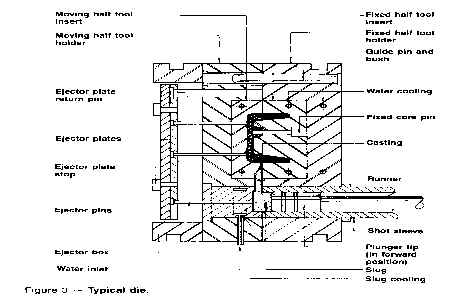
DIE TERMINOLOGY
Sprue holes are tapered with the small end located at the breaking point when the die is opened. A sprue pin, located in the ejector half, makes the sprue hollow and deflects metal entering the die into the runner system.
Runners are channels located at the parting line to route liquid metal from the sprue hole to the gate.
Gates are passages through which metal enters the die cavity. They have an important function in directing metal flow so that the cavity is correctly filled. Air is expelled through vents as molten metal enters the die cavity.
Guide pins assure proper alignment of die halves and correct register of cavities.
Side walls and cores are designed to have a slight taper or draft. The largest diameter or cross section of a cavity must be located at the parting line (unless slides are used) so the casting can be removed from the die. As molten metal in a die cavity solidifies, it shrinks away from walls onto core pins and other projections. The design of the die must permit withdrawal of core pins, and ejection without applying too much pressure which could cause deformation to the die casting.
Cores, fixed or moveable, as well as “loose pieces,” must be positioned to facilitate removal either mechanically or by hand. Loose pieces used to form undercuts must be positioned by the operator. This requires extra labor, and usually slows the casting cycle.
Inserts can be cast integrally to provide special characteristics.
Most dies are cooled by water circulating through channels drilled for that purpose
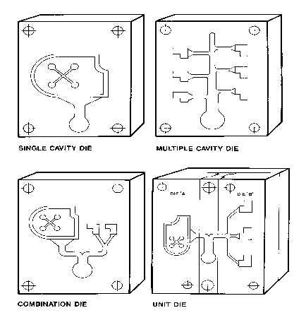
TYPES OF DIES
Dies are classified as: single cavity, multiple cavity, combination and unit dies (Figures 4-A to 4-D).
A single cavity die requires no explanation. Multiple cavity dies have several cavities which are all identical. If a die has cavities of different shapes, it’s called a combination or family die. A combination die is used to produce several parts for an assembly. For simple parts, unit dies might be used to effect tooling and production economies. Several parts for an assembly, or for different customers, might be cast at the same time with unit dies. One or more unit dies are assembled in a common holder and connected by runners to a common opening or sprue hole. This permits simultaneous filling of all cavities.
Figure 4
AUTOMATION IN DIE CASTING
“Automation and Mechanization” are terms often used interchangeably by the die casting industry. Automation of a manufacturing process is more sophisticated and complicated than the mechanization of various operations.
A die caster progresses towards automation by mechanizing various steps of the die casting process. For example:
- Die lubrication can be accomplished by installing fixed or reciprocating spray systems.
- An automatic ladling device can replace the hand ladle.
- Castings can be removed from the die by extractors or robots, or by “drop through” to a conveyor below the machine.
- Die casting machine operation can be integrated to cast, quench, trim and eject castings and return scrap to the furnace by conveyor.
By closing the loop, the die casting process can be automated, utilizing feed-back controls and microprocessors which automatically self compensate for process variables. As die casting plants move toward automation, noticeable changes occur. The operation tends to become safer. Production and quality improves considerably. Automation upgrades the labor force by requiring the development of new skills for machine set-up, programming, electronics, mechanics and maintenance.
QUALITY IN DIE CASTING
Quality in die casting is maintained through the use of process controls and feedback between the process control computer and the die casting machine.
Process controllers may utilize microprocessors to access transducers mounted on the die casting machine, to obtain velocity, position, hydraulic pressure and tie-bar strain data, etc. The microprocessor then adjusts the die casting machine operation through special valves, thus assuring consistent castings shot after shot. The process controller also collects machine performance data for statistical analysis in quality control.
CONTINUOUS COMPUTERIZED PROCESS MONITORING
Step 1 — Alarm monitoring — A computerized remote terminal mounted near the die casting machine continuously monitors the following: velocity, position, pressures at the accumulator, die lock-up cylinder, head and rod side of the injection cylinder, temperatures of hydraulic oil, metal (up to ten locations in the die), and strains on four tie-bars. Each of these variables is high/low limit checked every shot. An alarm is sounded or flashed if a casting variable goes out-of-limits.
Step 2 — Control — Automatic control valves and tie-bar adjusting motors are installed on the die casting machine and connected to the computerized remote terminal unit. The computer adjusts controls to maintain satisfactory die locking force, slow shot velocity, optimum fill time and proper intensifier timing. The computer may also be interfaced to a robot and/or a programmable controller.
Step 3 — Data acquisition — After installing computerized remote terminal units on each machine, a data acquisition system may be formed by interconnecting these units and communicating all information back to a master terminal computer in the office. The master computer prints out a management information report which summarizes the operation of the entire die casting shop, including which machines are running, when they stop, shots made (good and bad), which machines are out-of-limits and what to do. At the master station, the manager can analyze the process by studying shot profiles on a video monitor and statistical reports from a high speed printer.
- Advantages of Die Casting
- Die Casting Design
- Guides for Design
- Comparisons with Other Products
ADVANTAGES OF DIE CASTING
Die casting is an efficient, economical process offering a broader range of shapes and components than any other manufacturing technique. Parts have long service life and may be designed to complement the visual appeal of the surrounding part. Designers can gain a number of advantages and benefits by specifying die cast parts.
High-speed production – Die casting provides complex shapes within closer tolerances than many other mass production processes. Little or no machining is required and thousands of identical castings can be produced before additional tooling is required.
Dimensional accuracy and stability – Die casting produces parts that are durable and dimensionally stable, while maintaining close tolerances. They are also heat resistant.
Strength and weight – Die cast parts are stronger than plastic injection moldings having the same dimensions. Thin wall castings are stronger and lighter than those possible with other casting methods. Plus, because die castings do not consist of separate parts welded or fastened together, the strength is that of the alloy rather than the joining process.
Multiple finishing techniques – Die cast parts can be produced with smooth or textured surfaces, and they are easily plated or finished with a minimum of surface preparation.
Simplified Assembly – Die castings provide integral fastening elements, such as bosses and studs. Holes can be cored and made to tap drill sizes, or external threads can be cast.
DIE CASTING DESIGN
There are many sources for information on die casting design. These include text books, technical papers, literature, magazines, seminars and courses conducted by engineering societies, trade associations and industry. Often, the die caster selected to produce a component part is an excellent source for information.
To gain maximum advantage of the die casting process, it is always a good idea to draw upon the wide ranging experience of a custom die caster. New designs should be reviewed during the early stage of development. Significant savings may be realized during this interchange of ideas.
The data appearing (Table 5) on approximate dimensional and weight limits for die casting of different alloys may vary under special conditions. When in doubt, ask your die caster. He is thoroughly familiar with his machinery and equipment and can make suggestions (during the design stage) which may affect tooling and production changes, resulting in lower costs.
Table 5:
APPROXIMATE DIMENSIONAL* AND WEIGHT LIMITS FOR DIE CASTING IN DIFFERENT ALLOYS
Data apply to average conditions. For exceptional conditions, larger castings, closer dimensional limits and thinner sections may be feasible.
|
Type of Alloy (base metal) |
ZINC |
ALUMINUM |
MAGNESIUM |
COPPER |
|
Maximum weight of casting, lb. |
75 |
70 |
44 |
10 |
|
Minimum wall thickness, large castings, in. |
.035** |
.080 |
.100 |
.090 |
|
Minimum wall thickness, small castings, in. |
.015** |
.040 |
.040 |
.055 |
|
Minimum variation per inch of diameter or length from drawing dimensions over one inch *** |
.001 |
.0015 |
.0015 |
.009 |
|
Cast threads, max. no. per in. external |
32 |
24 |
24 |
10 |
|
Cored holes, min. dia., in.**** |
.050 |
.080 |
.080 |
.250 |
GUIDES FOR DESIGN
Advice on designing die castings is usually based upon desirable practices or situations to avoid. However, like most rules, there are exceptions. These affect either costs, appearance and/or quality of final products. Listed below are guides which should be considered when designing for die casting:
- Specify thin sections which can easily be die cast and still provide adequate strength and stiffness. Use ribs wherever possible to attain maximum strength, minimum weight.
- Keep sections as uniform as possible. Where sections must be varied, make transitions gradual to avoid stress concentration.
- Keep shapes simple and avoid nonessential projections.
- A slight crown is more desirable than a large flat surface, especially on plated or highly finished parts.
- Specify coring for holes or recesses where savings in metal and overall costs outweigh tooling costs.
- Design cores for easy withdrawal to avoid complicated die construction and operation.
- Avoid small cores. They can be easily bent or broken necessitating frequent replacement. Drilling or piercing small holes in die castings is often cheaper than the cost of maintaining small cores.
- Avoid use of undercuts which increase die or operating costs unless savings in metal or other advantages fully warrant these extra costs.
- Provide sufficient draft on side walls and cores to permit easy removal of the die casting from the die without distortion.
- Provide fillets at all inside corners and avoid sharp outside corners. Deviation from this practice may be warranted by special considerations.
- Die casting design must provide for location of ejector pins. Take into consideration the effect of resultant ejector marks on appearance and function. The location of ejector pins is largely determined by the location and magnitude of metal shrinkage on die parts as metal cools in the die.
- Specify die cast threads over cut threads when a net savings will result.
- Die castings which affect the appearance of a finished product may be designed for aesthetics, and to harmonize with mating parts.
- Inserts should be designed to be held firmly in place with proper anchorage provided to retain them in the die casting.
- Design parts to minimize flash removal costs.
- Never specify dimensional tolerances closer than essential. This increases costs.
- Design die castings to minimize machining.
- Where machining is specified, allow sufficient metal for required cuts.
- Consider contact areas for surfaces which are to be polished or buffed. Avoid deep recesses and sharp edges.
Dies can be produced for simple and complex parts. Parts having external undercuts or projections on side walls often require slides which increase costs. In many cases, however, resultant savings of metal or other advantages such as uniform wall sections, offset the extra cost or affect a net economy in overall costs. This is especially true when large quantities are involved.
COMPARISONS WITH OTHER PRODUCTS
Plastics injection moldings
Compared with plastic injection moldings, die castings are stronger, stiffer, more stable dimensionally, more heat resistant, and are far superior to plastics on a properties/cost basis. They help prevent radio frequency and electromagnetic emissions. For chrome plating, die castings are much superior to plastic. Die castings have a high degree of permanence under load when compared to plastics, and are completely resistant to ultra-violet rays, weathering, and stress-cracking in the presence of various reagents. Manufacturing cycles for producing die castings are much faster than for plastic injection moldings. Plastics, however, may be cheaper on a unit volume basis, may have color inherent properties which tend to eliminate finishing, are temperature sensitive, and are good electrical insulators.
Sand castings
Compared with sand castings, die castings require much less machining; can be made with thinner walls; can have all or nearly all holes cored to size; can be held within much closer dimensional limits; are produced more rapidly in dies which make thousands of die castings without replacement; do not require new cores for each casting; are easily provided with inserts die cast in place; have smoother surfaces and involve much less labor cost per casting. Sand castings, on the other hand, can be made from ferrous metals and from many non-ferrous alloys not suitable for die casting. Shapes not producible by die casting are available in sand castings; maximum size can be greater; tooling cost is often less and small quantities can be produced more economically.
Permanent mold castings
Compared with permanent mold castings, die castings can be made to closer dimensional limits and with thinner sections; holes can be cored; die castings are produced at higher rates with less manual labor; have smoother surfaces and usually cost less per die casting. Permanent mold casting involves somewhat lower tooling costs, and can be made with sand cores, yielding shapes not available in die casting.
Forgings
Compared with forgings, die castings can be made more complex in shape and have shapes not forgeable; can have thinner sections; can be held to closer dimensions and have coring not feasible in forgings. Forgings, however, are denser and stronger than die castings; have properties of wrought alloys; can be produced in ferrous and other metals, and in sizes not suitable for die castings.
Stampings
Compared with stampings, one die casting can often replace several parts. Die castings frequently require fewer assembly operations; can be held within closer dimensional limits; can have almost any desired variation in section thickness; involve less waste in scrap; are producible in more complex shapes and can be made in shapes not producible in stamped forms. Stampings, on the other hand, have properties of wrought metals; can be made in steel and in alloys not suitable for die casting, and in their simpler forms, are produced more rapidly, and may weigh less than die castings.
Screw machine products
Compared with screw machine products, die castings are often produced more rapidly; involve much less waste in scrap; can be made in shapes difficult or impossible to produce from bar or tubular stock; and may require fewer operations. On the other hand, screw machine products can be made from steel and alloys which cannot be die cast. They have the properties of wrought metals, and they require less tooling expense.
Die Casting Process Overview
The basic die casting process consists of injecting molten metal under high pressure into a steel mold called a die. Die casting machines are typically rated in clamping tons equal to the amount of pressure they can exert on the die. Machine sizes range from 400 tons to 4000 tons. Regardless of their size, the only fundamental difference in die casting machines is the method used to inject molten metal into a die. The two methods are hot chamber or cold chamber. A complete die casting cycle can vary from less than one second for small components weighing less than an ounce, to two-to-three minutes for a casting of several pounds, making die casting the fastest technique available for producing precise non-ferrous metal parts.
Die casting vs. plastic molding
Die casting produces stronger parts with closer tolerances that have greater stability and durability. Die cast parts have greater resistance to temperature extremes and superior electrical properties.
Die casting vs. sand casting
Die casting produces parts with thinner walls, closer dimensional limits and smoother surfaces. Production is faster and labor costs per casting are lower. Finishing costs are also less.
Die casting vs. permanent mold
Die casting offers the same advantages versus permanent molding as it does compared with sand casting.
Die casting vs. forging
Die casting produces more complex shapes with closer tolerances, thinner walls and lower finishing costs. Cast coring holes are not available with forging.
Die casting vs. stamping
Die casting produces complex shapes with variations possible in section thickness. One casting may replace several stampings, resulting in reduced assembly time.
Die casting vs. screw machine products
Die casting produces shapes that are difficult or impossible from bar or tubular stock, while maintaining tolerances without tooling adjustments. Die casting requires fewer operations and reduces waste and scrap.
Die Construction
Dies, or die casting tooling, are made of alloy tool steels in at least two sections, the fixed die half, or cover half, and the ejector die half, to permit removal of castings. Modern dies also may have moveable slides, cores or other sections to produce holes, threads and other desired shapes in the casting. Sprue holes in the fixed die half allow molten metal to enter the die and fill the cavity. The ejector half usually contains the runners (passageways) and gates (inlets) that route molten metal to the cavity. Dies also include locking pins to secure the two halves, ejector pins to help remove the cast part, and openings for coolant and lubricant.
When the die casting machine closes, the two die halves are locked and held together by the machine’s hydraulic pressure. The surface where the ejector and fixed halves of the die meet and lock is referred to as the “die parting line.” The total projected surface area of the part being cast, measured at the die parting line, and the pressure required of the machine to inject metal into the die cavity governs the clamping force of the machine.
Hot Chamber Machines
Hot chamber machines are used primarily for zinc, copper, magnesium, lead and other low melting point alloys that do not readily attack and erode metal pots, cylinders and plungers. The injection mechanism of a hot chamber machine is immersed in the molten metal bath of a metal holding furnace. The furnace is attached to the machine by a metal feed system called a gooseneck. As the injection cylinder plunger rises, a port in the injection cylinder opens, allowing molten metal to fill the cylinder. As the plunger moves downward it seals the port and forces molten metal through the gooseneck and nozzle into the die cavity. After the metal has solidified in the die cavity, the plunger is withdrawn, the die opens and the casting is ejected.
Cold Chamber Machines
Cold chamber machines are used for alloys such as aluminum and other alloys with high melting points. The molten metal is poured into a “cold chamber,” or cylindrical sleeve, manually by a hand ladle or by an automatic ladle. A hydraulically operated plunger seals the cold chamber port and forces metal into the locked die at high pressures.
Die Casting Tolerances
At Northwest Die Casting, we look at tolerances differently. We set standards that both meet and exceed those of the industry and are used as a guideline for our designers. We have a belief that tolerances should be as tight as necessary, but not as tight as possible.
We look at what’s needed to meet functional requirements and what dimensions and features are critical. Then we select the process that will achieve them.
When looking at tolerances we assess the following:
- The form of the part
- The proximity of the feature within the tool
- Its relation to other features on the part
Tool life and wear is taken into consideration as this will affect short-term versus long-term process capabilities.
Moving Die Components

Linear Dimensions

Parting Line

At what point do tolerances require machining instead of as-cast die casting?
Die Casting Tolerances
We look at tolerances differently. Our standards both meet and exceed industry standards and are used as a guideline for designers worldwide. We believe that tolerances should be as tight as necessary, not as tight as possible.
We don’t believe the most important factors are how tight the tolerance can be or the process capability that can be achieved. Instead, we look at what’s needed to meet functional requirements and what dimensions and features are critical. Then we choose the process that will achieve them.
When we look at tolerances we carefully assess:
- The form of the part
- The proximity of the feature within the tool
- Its relation to other features on the part
We always take into consideration tool life and wear as this will affect short-term versus long-term process capabilities.
Moving Die Components
Linear Dimensions
Parting Line
At what point do tolerances require machining instead of as-cast die casting?
“With aluminum & zinc die casting, we can achieve the tightness tolerances without any secondary machining.”
In aluminum, we can cast an internal diameter to within +/- 100 microns.
In zinc, we could do that at half that tolerance +/- 50 or even +/- 25.